Friday 25 March 2022


How to convert higher version AutoCAD files into lower version using AutoCAD DWG TRUEVIEW, stepwise process.


STEP – 1: Installing AutoCAD DWG TRUEVIEW:

If you already do not have AutoCAD DWG TRUEVIEW software installed in your system (laptop/desktop) then please download the same using AUTODESK website free download viewers page (https://www.autodesk.in/viewers).


Note: Autodesk provides DWG TRUEVIEW as free to view or convert AutoCAD files into older version.

Step – 2: Converting a higher version file in to lower version

1.      Launch AutoCAD TRUEVIEW from start menu or desktop shortcut (in our example we are using AutoCAD TRUEVIEW 2022 Version).

2.      On top left corner look for the DWG Convert icon as highlighted in below given image & click it.


3.      Now upon clicking above icon below given DWG convert window will appear on screen.


4.      In above DWG Convert window look for AutoCAD symbol button at bottom (Highlighted circle). Click on the same to open AutoCAD files you want to convert to lower version, it will open window for selecting files browse & choose your required files (Note: Multiple AutoCAD files can be opened by selecting all files inside the folder).

5.      Now after importing/opening AutoCAD files as explained above the window will appear as shown below with files tree list populated with imported files.


6.      Now, check on right side of the window it shows conversions setups available from the same choose the file version you want the selected AutoCAD files to be lowered to. In our case we are choosing “Convert to 2007 (in-place)”. Here “in-place” refers to the fact that all the files will be converted to selected lower version & will be replaced at original saved location. Now let’s proceed with conversion, click on convert to do the same.

7.      Now, after completion of all above steps your files have been converted in to the selected lower AutoCAD version at original saved location now you can use the same.


****


Friday 21 September 2018

Load Calculation for Design of RCC Frame Buildings


Loads In Buildings:
In Building construction during design of RCC/Steel structures the frame systems are designed to withstand the loads which the building will serve for its design life. In this post i will illustrate the basics of the design loads considered while designing of structures & the basic mathematics involved in their calculation.
Types of building loads:
In a typical residential building as discussed below the following given loads are present;
1.   Dead Load – Under this category all the load of the dead or non-moving/stationary/fixed elements of the building are considered such as dead weight of walls, weight of roof/floor finishes, self weight of structural members such as; beams, coloumns, Footings & RCC slabs etc. The calculation of live loads has to be done by taking properties of the material & the dimensions of the element considered.
2.    Live Load – In live load category the moving loads such as due to human use or furniture or any other mechanical equipment are considered. For all general categories live loads are defined in Indian Code IS 875 Part-3 rest if any shall be calculated as per the requirement.
3.  Dynamic Load – Apart from dead & live loads a building structure is also subjected to application of dynamic load. Dynamic loads are the loads in which the value & nature of application of force is not constant throughout & is subjected to changes as per the conditions governing the forces. Forces due to wind, earthquake, traffic or heavy machinery (such as blowers or pumps) falls under this category.
Dead Loads:
1.       Self weight- It is the weight of the frame or the individual weight of the structural elements such as Beams, Columns & Slabs. In computer programs such as STAAD Pro inbuilt capability is there which allows the program to calculate the self weight of the elements automatically in accordance with the shape, size & member dimensions.
Example: Below given are the examples for manual calculation of self-weight of the structural elements.
a.       Beam: Let it be of any shape Rectangular/square/tee/trapezoid anything for calculation of weight use the given formula;
Weight of member = cross section area of member x length of member x RCC density
For a 0.3 m wide 0.45 m deep beam section of 5 m clear length & material density = 25 kn/m3 (for RCC), the weight will be;
Weight of beam = (0.3 x 0.45) x 5 x 25 = 16.875 Kn
The above calculated weight of 16.875 Kn is the total weight which can be further converted into Uniformly Distributed Load (UDL) by dividing the total weight by member length.
UDL = 16.875/5 = 3.375 Kn/m
b.      Column: Same as explained above the self-weight of a column can be calculated only the terminology of member length will be changed to member height & the weight of column will be calculated as point load only its conversion in UDL is not required.
c.       Slab: RCC slabs, the weight of roof slabs is applied as uniform pressure in Kn/m2. For analysis purpose it is we consider a 1 m x 1 m square section & calculate the volume of the RCC & then the same is multiplied with the density for derivation of pressure in kn/m2.
Weight of slab = (1 x 1 x slab thickness) x RCC density
In the above formula as (1 x 1) doesn’t effects the calculation thus it can be further simplified as;
Weight of slab = slab thickness x RCC density

For 0.15 m thick slab the calculation will be as follows;
Weight of slab = 0.15 x 25 = 3.75 Kn/m2
In the above calculation of RCC slab weight further additional load due to floor finishes are to be included generally for stone/cement floorings 0.75 kn/m2 to 1.5 kn/m2 is considered.
Distribution of slab load on supporting beams:
Depending upon the arrangement of beams (square or rectangular) triangular or trapezoidal shape distribution is carried out. For example (refer fig-1 below) in case of a rectangular slab of 6 m x 4 m the longer side beams spanning between A-B & D-C will carry the load of corresponding trapezoidal portion whereas the shorter span beams spanning between A-D & B-C will support weight of roof slab coming from corresponding triangular region.
Load on 6 m span = area of trapezoid x thickness of slab x density
Load on 6 m span = 8 x 0.15 x 25 = 30 Kn = 30 / member length = 30/6 = 5 Kn/m
The above calculated load of 30 Kn can be further converted in UDL of 5 kn/m by dividing it by member length as shown above.
Load on 4 m span = area of triangle x thickness of slab x density
Load on 4 m span = 4 x 0.15 x 25 = 15 Kn = 15 / member length = 15/4 = 3.75 Kn/m
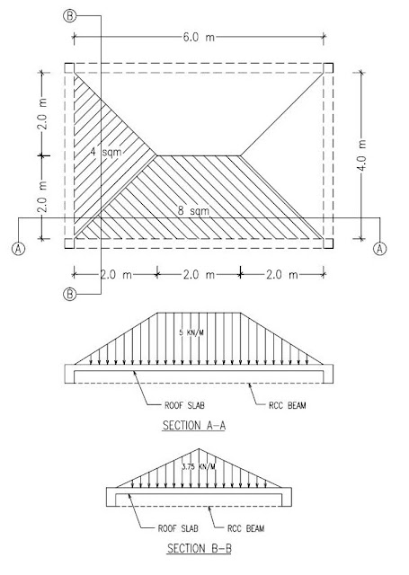
Fig-1 Load distribution of slabs on supporting beam members/load bearing walls


Above discussed was the case of rectangular slab whereas in the case of square slab the slab plan will be divided in 4 nos. of equal triangles & the load for the same will be transferred to the corresponding beam members.

d.      Walls: Generally in building construction brick walls of single brick (0.115 m thick) & double brick (0.230 m thick) are used, the load of brick walls is calculated as follows;
Weight of wall (In KN/m) = Height of wall x thickness of wall x density of brick/stone masonry
For 0.23 m thick wall of 3.2 m clear height the load will be;
Weight of wall (In KN/m) = 3.2 x 0.230 x 22 = 16.192 Kn/m
The above calculated load of 16.192 Kn/m will be applicable in the form of UDL on the beam members supporting the brick wall, in above calculation brick wall density considered is 22 Kn/m3.
Live Loads:
Live loads or imposed loads as per building type & occupancy classification shall be provided as per Indian Code IS 875 Part-2 in table-1.

Dynamic Loads:
Mainly, the RCC buildings are subjected to two dynamic forces;
  1. Wind Force: To be calculated in line with the provisions of IS 875 (Part-3).
  2. Seismic/Earthquake Force: To be calculated in line with the provisions of IS 1893: 2016.
methodology for calculation of wind forces & earthquake forces will be discussed in separate post, keep following.

Hope above given explanation helps in understanding the basics for determination of dead & live loads as per Indian Code.

Regards
Alok Dixit


Monday 17 September 2018

Member Release in STAAD Pro


Moment Release in STAAD Pro:
In the given illustration a bay frame with 5 m length, 5 m width & 3 m height is considered & between two primary beams (beams which are supported directly over columns) on secondary beam (beam supported over primary beam) is provided.
The secondary beam is loaded with 20 Kn/m UDL, no other weight is considered on any other members.

Fig.1 Bay frame with Loading & beam numbers

Case-1:
when the secondary beam is fixed at joints at primary beam & no release command is given.

Bending Moment:
If you notice in the below given figure-2 you can see that hogging moments are coming on the top face of the secondary beam near the joints, this is because when this beam under loading tries to undergo bending in downward direction the rigidity of the joint at secondary & primary beam junction restrains it & thus because of this restraining action hogging moments arise on the top face of the secondary beam.

Fig.2 Bending Moment Diagram

Torsion:
Moreover due to rigidity at joint the secondary beam also tries to rotate the primary beams about their own axis in inward direction which will result in arise of torsional moments in the primary member (refer figure-3). Upon analysis in the given condition the joints are treated as rigid offering restraints to all three force directions (Fx, Fy & Fz) & all three moment directions (Mx, My & Mz) & thus torsion or twisting moment about the local axis of primary beams is generated. In the given case 11.51 Knm torsional moment is coming in primary members.

Fig. 3 Torsional Moments in Primary Members when supported secondary beam is not released

Fig. 4 Torsional moments coming in primary members in un-released condition

Case-2:
When secondary beam is released at joints & is assumed to be simply supported over the primary beams.
In this case secondary beam has been provided with member release command & bending moment about Z i.e. MZ moment is released (you can notice two tiny circles near joints denoting member release command), in our case we have considered 100% release.

Bending Moment:
When a member is released at a joint then STAAD will not consider that joint as a rigid joint/node offering restraints in all three force directions (Fx, Fy & Fz) & all three moment directions (Mx, My & Mz) & instead it will release the force or moment restraint as defined in member release command. In this case as we said above we have given member release in Mz, so all the bending moment in Mz is free (without restraint) & due to this the behaivour of the beams has changed & because of that only sagging moments (as in the case of simply supported member) are coming on the bottom face of the beam & no hogging moments will come (refer figure-5).

Fig. 5 Bending moment when secondary beam is released


Torsion:
Now as the condition of the joint is simply supported & with no restraint offered by primary beams to the secondary beam in bending the secondary beam undergoes bending freely & thus no torsion or twisting of primary members happen, that means zero torsion in primary members.


Fig. 6 Zero torsion in primary members supporting secondary beam with member release command


Conclusion: Below given is the comparative analysis of the above two cases;

S.no.
Point Observed
Joint conditions
Remarks
Without Member Release command
With member release command (100% release in Mz)
1.
Rigidity at the joint & support condition
Fixed Support condition.
STAAD Pro treats the Joint/node as rigid & thus upon analysis restraints is provided in all three force directions (Fx, Fy & Fz) & all three moment directions (Mx, My & Mz).
Simply Supported condition.
With release command the joint is released in the specified force or moment & thus no restraint is offered for the same, in our case Mz release is used.

2.
Hogging Moment in Secondary Beam at Top face near supports.
23.02 KNm
0.0 Knm
Reinforcement at top will be more in without member release command.
3.
Sagging moment at bottom mid face of the secondary beam.
-39.48 knm
-62.50 knm
Reinforcement at bottom face of the beam will be higher in member released case due to concentration of moments at bottom face.
4.
Torsion In primary beams.
11.51 Knm
0.0 knm
In without member release case the nos. of the stirrups or transverse reinforcement will be increased in primary beams i.e. stirrups will be required at closer spacing.
5.
Bending moment & shear force in primary beams.
Same
Same

1.  Generally, member release command is given in conventional design practice whenever the primary beam member fails because of torsional moments.
2.     Although it is conventional but it is always advised to make sure that the assumption of member release holds true as per the actual conditions of the structure.

3.   Member release shall be avoided because it causes reduction in nos. of stirrups of the primary member & which in turn reduces the ductility of the member, further the concrete & main reinforcement of beams with less no. of stirrups then required will not be confined properly. Poor ductility & poor confinement is not good for the structure for its resistance to seismic forces. 

Any further queries or suggestion, kindly drop in the comment section below.

Regards
Alok Dixit 

Wednesday 12 September 2018

WHY EXTRA BARS AT TOP ENDS & BOTTOM MID ARE PROVIDED IN BEAMS

Extra top & bottom reinf. are provided as per the Ast requirement of the beam as per design, generally, in continuous frames beams undergo hogging moments at top face (max. in L/4 region from the face of the column) & sagging moments at the bottom middle region & thus the concentration of bending moments is greater in the aforesaid regions. Now while designing you have got two alternatives;
(no.1) Either to provide same steel throughout the top & bottom face or (no.2) to provide steel required for extra hogging/sagging moments at respective faces as extra.
choosing option no.2 gives economy & it fulfills design requirements as well thus, extra steel at top & bottom face is provided as per design requirements to cater the extra moments.
further kindly refer attached image for clarification & better understanding of above.
Regards
Alok Dixit

CONCRETE QUANTITY & LOAD CALCULATION IN DOG LEGGED STAIRCASE

Calculating the quantity/volume of concrete in the staircase is simple mathematics, in the given example 1 m width of the dog-legged staircase with two flights with a total rise of 3.3 m is considered. The riser is 0.15 m & Tread is 0.25 m whereas landing is assumed as of 1.0 m length.
Kindly refer attached image for calculation example.
STAIRCASE LOAD/CONCRETE QUANTITY CALCULATION

Thanks & Regards
Alok Dixit

SIDE FACE REINFORCEMENT IN BEAMS AS PER IS 456 (INDIAN CODE)

For beams exceeding the depth of 750 mm Side Face Reinforcement is provided to ensure lateral stability as well as confinement to increase the ductility of the beam member. Moreover, this additional side face reinforcement which is not included in load sharing mechanism also helps in dissipation of additional forces.
In general practice as per IS 456:2000 clause 26.5.1.3 gives the guidelines for the provision of side face reinforcement in beams in which web thickness is greater than 750 mm. kindly refer attached image for further clarification.

Apart from above stated general guidelines, if the concerned beam member is subjected to considerable lateral forces than it shall be analyzed as per the conventional method which we use for forces along the depth the same shall be used for calculation of moments due to the forces applicable along the width of the member.


Regards
Alok Dixit

Wednesday 27 June 2018

UNIT CONVERSION

MEASUREMENT UNITS USED IN CONSTRUCTION INDUSTRY:
In construction industry two type of measurement systems are prevalent;
1.       SI or Metric unit system: In this system the following units are used for length, area & volumetric measurements;
a.       Length  : meter (m), centimeter (cm), millimeter (mm) etc.
b.      Area                      : sqm (m2), sqcm (cm2), sqmm (mm2) etc.
c.       Volume                : m3, cm3, mm3 etc.        
2.       Imperial unit system: In this sytem the following units are used for length, area & volumetric measurements;
a.       Length  : yard (yd), feet (ft), inches (in) etc.
b.      Area                      : sq.yard (yd2), sqft (ft2), sqinch (in2) etc.
c.       Volume                : cu. Yard (yd3), cu. ft (ft3), cu. Inch (in3) etc.

Conversion Tables:
Length
Imperial units of measurement.
1 foot (ft or ‘)
=
12 inches (in or ")
1 yard (yd)
=
3 feet
1 mile
=
1,760 yards


Metric units of measurement.
1 centimetre (cm)
=
10 millimetres
(mm)
1 metre (m)
=
100 centimetres
1 kilometre (km)
=
1,000 metres
Converting from Imperial to metric measurements.
1 in
=
25.4 mm
1 in
=
2.54 cm
1 ft
=
0.3048 m
1 yd
=
0.9144 m
1 mile
=
1.6093 km
Converting from metric to Imperial measurements.
1 mm
=
0.0394 in
1 cm
=
0.3937 in
1 m
=
3.2808 ft
1 m
=
1.0936 yd
1 km
=
0.6214 miles


Area
Imperial units of measurement.
1 sq foot (ft2)
=
144 sq inches (in2)
1 sq yard (yd2)
=
9 sq feet
1 acre
=
4,840 sq yards
1 sq mile
=
640 acres
Metric units of measurement.
1 sq cm (cm2)
=
100 sq mm (mm2)
1 sq metre (m2)
=
10,000 sq cm
1 sq km (km2)
=
100 hectares
Converting from Imperial to metric measurements.
1 in2
=
6.4516 cm2
1 ft2
=
0.0929 m2
1 yd2
=
0.8361 m2
1 acre
=
4046.9 m2
1 mile2
=
2.590 km2
Converting from metric to Imperial measurements.
1 cm2
=
0.1550 in2
1 m2
=
10.7643 ft2
1 m2
=
1.1960 yd2
1 m2
=
0.0002 acres (not used)
1 km2
=
0.3861 mile2
Volume/Capacity
Imperial units of measurement.
1 cu foot (ft3)
=
1,728 cu inches (in3)
1 cu yard (yd3)
=
27 cu feet (ft3)
1 pint (pt)
=
20 fluid ounces (fl oz)
1 gallon (gal)
=
8 pints
Metric units of measurement.
1 cu decimetre (dm3)
=
1,000 cu cm (cm3)
1 cu metre (m3)
=
1,000 cu decimetre
1 litre (l)
=
1 cu decimetre

Converting from Imperial to metric measurements.
1 in3
=
16.387 cm3
1 ft3
=
28.3286 dm3
1 ft3
=
0.0283 m3
1yd3
=
0.7646 m3

Converting from metric to Imperial measurements.
1 cm3
=
0.0610 in3
1 dm3
=
0.0353 ft3
1 m3
=
35.3357ft3
1 m3
=
1.3080 yd3
1 ml
=
0.0352 fl oz
1 l
=
1.76 pints (UK)
1 l
=
0.220 gallons (UK)
1 hl
=
21.997 gallons (UK)